Piecewise-Focusing (PWF) Collectors
for high-temperature CST power and heat
DISCUSSION
Depending on the solar multiple, the cost of heliostats plus central receiver represents around 40% to 70% of the total cost of a CST central receiver power station with thermal storage. Therefore the collector system offers the greatest scope for reduction in the cost of CST power.
[Solar multiple is 1.0 when the collector system is sized to supply heat to the power block for continuous operation at rated power when the sun is high enough in the sky, say 8 or 9 hours per day average. A solar multiple of 2.0 (for example) would allow a further ~8 hours of operation via thermal storage.]
How to reduce the cost of a CST collector system:
- Reduce the required area of reflectors.
- Reduce the cost per unit area of reflector.
1. PWF systems need considerably less reflector area.
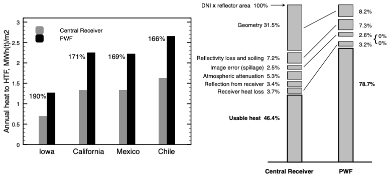
As shown above left, the output from a PWF system is 65% to 90% greater than output from a central receiver system. Consequently the required area of PWF reflectors is only 55% or 60% of the heliostat area in a central receiver system. The better performance results partly from lower reflection from the receiver and the near-absence of atmospheric dispersion/absorption (see diagram above right), and most importantly the average cosine factor for the reflectors is much better than for heliostats.
See Ref [2] for more information.
2. PWF collectors may cost less than heliostats plus receiver, per unit area of mirror.
Although heliostats have been in use for several decades, there's still a lot of research going on to make them less expensive, e.g. build them out of concrete(??), and trying to make them work better, e.g. aim them more reliably, or focus them more accurately. PWF collectors cut through these problems by eliminating heliostats altogether.
About half the cost of a heliostat goes into the mirror and the mirror backing; the other half goes into the two-axis gear drives, support pedestal, and foundation. For a PWF reflector, the mirror and backing are quite similar, but the reflector is mounted on the base-frame with a couple of short struts and simple bearings, and it is rotated with an ordinary linear actuator. This arrangement is straightforward and inexpensive. The cost of the base-frame is unlikely to exceed the cost of the 200 or more sets of foundation, pedestal and two-axis gear drives that would otherwise be needed.
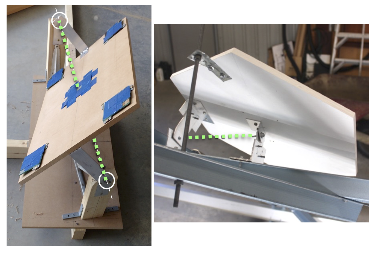
In most cases the reflector is at an angle to its axis of rotation, but it's an axis, not an axle. Two methods of defining the axis are shown in the photos above, in which the axis is indicated by the green dashed lines. On the left, struts extend to both the front and rear of the [rectangular] reflector, and the [hexagonal] reflector on the right has a central mounting point instead of the forward strut. It also has a threaded rod to control rotation, emulating a linear actuator.
RECENT WORK
The absorber
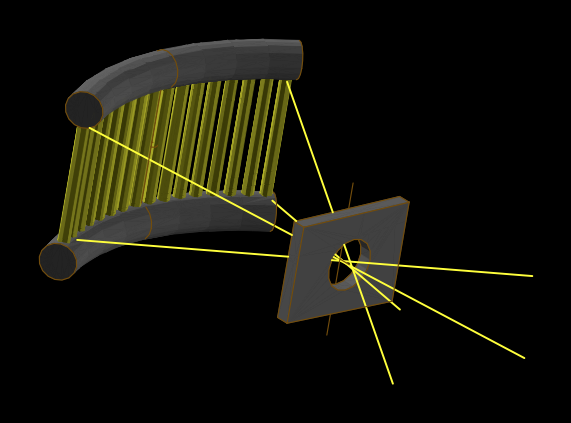
... is the region of the receiver that converts concentrated sunlight into useable heat, usually implemented as a bank of tubes carrying a heat transfer fluid. A cavity receiver is a bit like a pinhole camera, in that the illuminated absorber area follows the overall shape of the face of the collector. Earlier PWF work using a paraboloidal face (circular aperture) therefore needs a roughly circular (radially symmetric) absorber, e.g. the inside of a cone or section of a sphere. Implementing this absorber as a bank of tubes with inlet and outlet manifolds would be a plumber's nightmare. The face shape of the "Physical model with planar face" is a rounded rectangle, so the absorber should also be roughly rectangular (not necessarily planar). This can readily be implemented as a 'billboard' absorber inside the cavity, possibly with cylindrical curvature as shown above.
Spherically-curved reflectors
During early stages of PWF collector conceptualization and design it was assumed that each reflector would be curved three-dimensionally such that it would be perfectly focused on the receiver entrance at a selected sun elevation, i.e. the curvature of each reflector would be customized and different from the others -- probably expensive to manufacture. What if reflectors are all made with spherical curvature? Mass production would be much cheaper. And since the best radius of curvature depends on the distance to the receiver, how many different radii of curvature would be needed across the whole array of reflectors?
The first three images below show some results for spherical reflectors at the indicated sun elevations. Each small circle represents a ray reflected from the centre or six vertices of each of the eight reflectors of the "Physical model with planar face", allowing for spread caused by the finite size of the sun, but with no allowance for random errors in mirror shape. Three different radii of curvature were used across the eight reflectors. The large dashed circle represents the receiver entrance. The two further images are corresponding results from reflectors with custom curvature; the 'perfect' result at 40 degrees elevation is not shown.
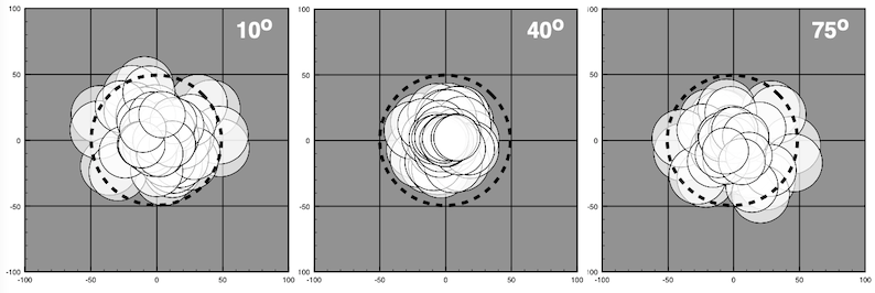
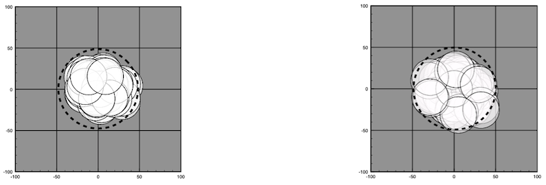 The use of spherical reflectors does degrade reflector focus to a moderate extent, although only a few 'worst case' reflectors actually cause the visible spillage. However, this can be mitigated by using a greater number of relatively smaller reflectors, e.g. 250 instead of 90 reflectors on the whole collector front face. For a total collector area of 5000 m2, each reflector would be 5000/250 = 20 m2, probably a good size for manufacturing.
Updated April 2025.
*****************